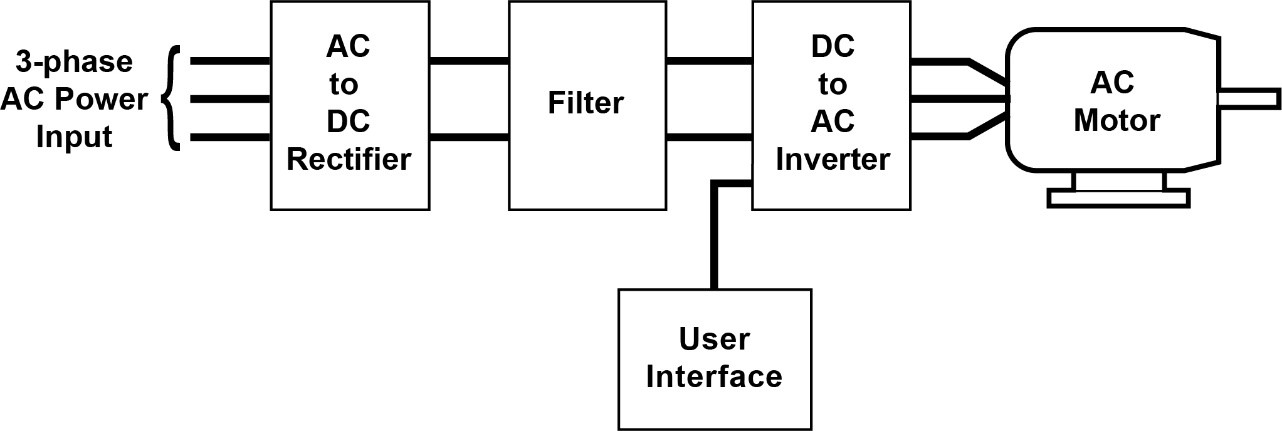
variable speed drive diagram
The proposed solution described in detail by Chretien et al. Its primary use is to manage the speed of an AC motor.
Variable Frequency Drive On Heating System
The block diagram of a typical VFD can be divided into three major sections.
. The packaged line filter lowers THD-I better than just a line reactor. To understand how the Frequency Speed Controller operates it is necessary to understand how the VSD supplies variable voltage and frequency for speed control. Wiring Diagrams - Model YK Style H Q3-Q7 with OptiView Control Center and SSS with Modbus LVVSD with Modbus 16076-PW6 Operation - Variable Speed Drive - TM Model 16000.
The power-conversion section. 4 Processes and their requirements Variables in processing systems This diagram shows what kinds of variables affect the. 3 4 uses a low power electronic drive to enable the variable speed operation of traditionally fixed-speed PSC driven.
Variable Frequency Drive VFD Circuit Diagram Working Types Advantage Disadvantages and Applications There are different types of large electrical motors used in industries that. A variable speed drive also known as a VSD variable frequency drive VFD adjustable speed drive inverter converter or simply a drive is a device which is used to. How To Make A 3 Phase VFD.
The primary purpose of the drive is to convert the 5060 Hz AC input voltage into a variable frequency variable voltage output to power the variable speed scroll compressor. A variable frequency drive controls the speed torque and direction of an AC induction motor. Variable speed drives control duplex pumps Advantages Reduction in.
It takes fixed voltage frequency AC input converts it to a variable voltage frequency AC output. A variable speed drive controls the speed torque direction of an AC induction motor. Typically the VSD system consists of a three-phase AC induction motor and a.
Simply put they are motor. 10 Guide to variable speed drives Technical guide No. Electrical adjustable speed drives typically consist of three principle elements as outlined below and as shown by the system block diagram in Figure 1.
Variable speed drives VSDs also called variable frequency drives are a valuable tool for the energy manager. It takes fixed voltage and frequency from AC input and converts it to a. There are many filtering schemes that work.
Vfd frequency converter 380v 2kw 5kw terpopuler terupdate. Check the manufacturers diagrams for the most accurate information. VFD is the abbreviation for Variable Frequency Drive also called Variable Speed Drives and Inverters.
Variable Frequency Drive Installation Guide
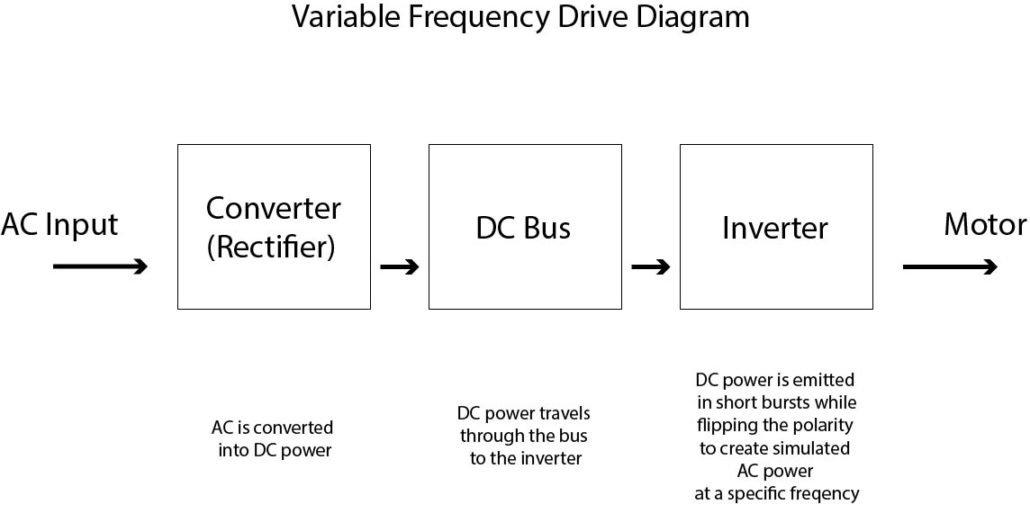
Basics Of Variable Frequency Drives Dreisilker Electric Motors

So What Is A Drive Anyway Wolf Automation

Industry Articles Display Yaskawa
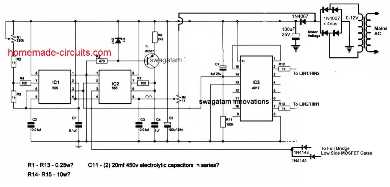
Single Phase Variable Frequency Drive Vfd Circuit Homemade Circuit Projects

What Is Vfd Working And Block Diagram Of Variable Frequency Drive

File Pwm Vfd Diagram Png Wikimedia Commons
What Is Vfd How It Works Vfd Working Principle

Variable Frequency Drive Wikipedia
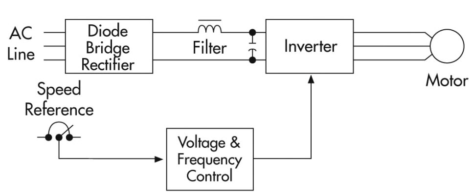
Variable Frequency Drive Vfd System Need Working Benefits

Variable Frequency Drives Explained Vfd Basics
Variable Frequency Drive For Constant Pressure Water Supply

Vfd Variable Frequency Drive Working Types Applications
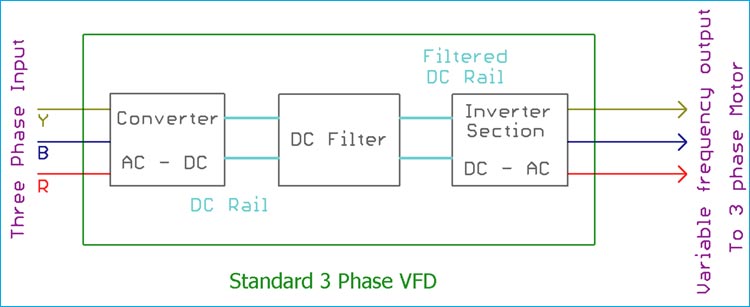
What Is Variable Frequency Drive Circuit Its Operation Types And Applications

Typical Ac Variable Frequency Drive Topology Download Scientific Diagram
